

Alloy Resistor Recommended List for Precision Circuit Designs
2026-08-13
Precision circuit design lives and dies by the passive components you barely think about—especially resistors. Get the alloy wrong, and your 24-bit ADC reading turns into a temperature-dependent guess. This recommended list cuts through the datasheet noise, spotlighting alloy resistors that actually deliver stability in high-resolution front-ends. If you're after ppm-level repeatability instead of marketing specs, you're in the right place. And when you need to dig into specific part numbers, Milliohm offers the detailed comparisons we rely on.
Current Sense Paths Where Low TCR Alloys Prevent Measurement Error
In precision current sensing, the shunt resistor sits directly in the current path, and any drift in its resistance translates immediately into a voltage error across the sense terminals. Low TCR alloys such as Manganin or Zeranin keep this resistance nearly constant even as the shunt heats up from the current flowing through it. That stability matters most in high-current paths where self-heating can easily push a resistor 50°C or more above ambient—without a low TCR material, the apparent current reading would shift by several percent over the course of a single load cycle.
Battery management systems and motor phase sensing are two places where this error becomes costly. In a battery pack, state-of-charge calculations depend on coulomb counting through a shunt; if the shunt's resistance changes with temperature, the accumulated error grows over time and misleads the fuel gauge. Similarly, in a motor drive, the phase current shunt sees rapid load changes and uneven cooling across the PCB. A low TCR alloy keeps the sense voltage proportional to actual current, not to the local hot spot near a switching MOSFET.
Another less obvious current sense path is the PCB trace itself used as a sensing element. Copper has a TCR around 3900 ppm/°C, so a 20°C temperature rise changes its resistance by nearly 8%. Designers who try to save cost by using a copper trace as a current shunt often end up with measurements that drift with board temperature. Replacing that trace section with a dedicated low TCR alloy shunt—or even a small strip of resistive alloy—breaks the link between temperature and measured current, making the sense path predictable across the full operating range.
Feedback Networks That Demand Tight TCR Tracking Between Pairs
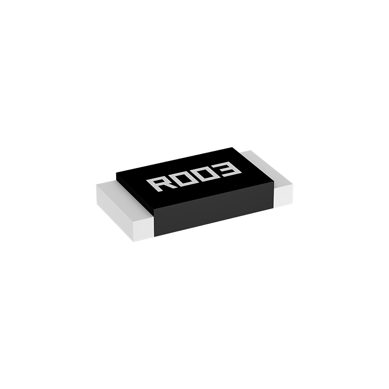
In precision analog circuits, feedback networks often rely on resistor pairs whose temperature coefficients must track each other almost perfectly. A slight mismatch in TCR between two nominally identical resistors can introduce gain drift that becomes glaringly obvious over a wide operating range. Designers therefore select thin-film resistor arrays or matched networks where the materials and thermal coupling guarantee that both elements move together as temperature swings.
The demand for tight TCR tracking becomes especially critical in differential amplifiers and instrumentation front ends. Here, the feedback ratio is set by the ratio of two resistors, and any differential change in resistance directly corrupts the common-mode rejection. Even a few ppm/°C of uncorrelated drift can turn a high-precision circuit into a mediocre one, forcing engineers to place the pair in close physical proximity and often on the same silicon substrate.
Achieving this level of tracking rarely happens by accident. It requires deliberate layout symmetry, avoidance of thermal gradients from nearby power devices, and sometimes laser trimming after packaging. When done right, the feedback network becomes almost invisible in the error budget, letting the active devices dominate the performance limits rather than the passive components that surround them.
Input Attenuators: Why Thermal EMF Outweighs Tolerance Here
When signal levels drop into the millivolt or microvolt range, the resistor tolerance in an input attenuator stops being the primary concern. A 0.01% mismatch might shift the attenuation ratio slightly, but that error is stable, predictable, and often removable through a simple calibration routine. Thermal EMF, on the other hand, behaves like a random offset that changes with every temperature gradient across the attenuator network.
Inside a typical attenuator, every junction between dissimilar metals—relay contacts, solder joints, resistor leads, PCB traces—can generate a thermoelectric voltage. Even a fraction of a degree Celsius difference across such a junction produces several microvolts. Those microvolts sit directly in series with the input signal, so they are not attenuated; they pass through at full strength and corrupt the measurement before any scaling takes place.
The real problem is that thermal EMF cannot be calibrated away in the same manner as a fixed resistance error. It drifts with ambient temperature, airflow, and the thermal time constants of nearby components. A design that focuses only on tight resistor tolerances may still show errors many times larger than expected because a few poorly placed junctions are generating thermal offsets. For input attenuators, managing those junctions—keeping materials matched, minimizing temperature differences, and avoiding unnecessary connections—becomes far more important than chasing another digit of resistance accuracy.
Reference Scaling Stages That Need Decades-Long Load-Life Stability
When scaling reference stages for prolonged mechanical duty, the real challenge isn't initial precision but how that precision survives year after year of cyclic loading. Tiny geometric shifts, micro-wear at contact interfaces, or creep in preloaded joints can accumulate enough error to invalidate a reference stage long before a catastrophic failure occurs. That's why material selection and thermal treatment often matter more than the visible machining tolerances.
Decades-long load-life stability demands a different mindset from short-term qualification. Instead of chasing sub-micron repeatability over a few thousand cycles, engineers must focus on passive drift suppression: using stress-relieved castings, matched thermal expansion pairs, and deliberately conservative bearing preloads that leave margin for relaxation. Periodic recalibration can mask some of this, but a reference stage that drifts predictably and slowly is far more useful than one that stays perfect until it suddenly shifts.
Field data from long-running metrology installations shows that the stages which survive thirty years of intermittent loading are rarely the stiffest or the most complex. They tend to be slightly overbuilt in the load path, with generous contact areas and redundant constraint where possible. The goal is to make the stage boring—no dramatic wear-in phase, no sensitivity to humidity cycles, just a stable metrological backbone that quietly holds its datum while everything else around it changes.
High-Temperature Board Zones: Derating Alloy Resistors on Real Layouts
The datasheet derating curve assumes a fairly uniform ambient temperature, but real boards rarely behave that way. Alloy resistors placed near voltage regulators, MOSFETs, or inductors can sit in hot pockets that run 20°C to 40°C above system ambient. If you only derate for inlet air temperature, you may still push the resistor past its safe operating point. Map the board into thermal zones first, and treat each zone as a separate ambient for derating purposes.
Measure the actual resistor body temperature under full load before settling on a power rating. A thermal camera or a fine-wire thermocouple on the resistor terminal works better than a nearby board sensor. Pay attention to areas with poor airflow, such as under tall connectors or between rows of capacitors. If the local board zone stays hot even when the average system temperature is moderate, add extra derating margin to the resistor power calculation.
In dense layouts, wider copper pads and thermal vias can pull heat away from the resistor, but only if the connected plane is not itself hot. If the adjacent copper pour is already saturated, it stops acting as a heat sink. In those high-temperature zones, consider a larger case size, split the current across parallel resistors, or move the sense resistor to a cooler area of the same net. Then verify resistance drift at full load instead of relying on a single derating percentage from the datasheet.
Humidity-Exposed Nodes: Package Selection for Long-Term Precision
Choosing a package for nodes that live in damp air is less about picking the highest IP rating and more about understanding how moisture moves through materials over months and years. A housing that seals perfectly on day one can still breathe through cable glands, connector bodies, or micro-voids in potting compound. Once vapor gets inside, it condenses during temperature swings and settles on exposed pads, causing dendritic growth or leakage currents that quietly shift sensor readings.
Long-term precision depends on the internal microclimate you create, not just the barrier you put around it. Conformal coatings help, but they introduce their own failure modes if applied unevenly or if they trap flux residues underneath. Better results often come from pairing a low-permeability enclosure with a desiccant or a small heater to keep the internal relative humidity below the dew point. The goal is to avoid the narrow band where moisture, voltage, and ionic contamination meet.
Field data from nodes deployed near coastlines shows that failures cluster around connector interfaces and seams, even when the enclosure itself remains intact. For that reason, package selection should start at the interconnect: pick contacts with sufficient wipe and a sealed backshell, then work inward. If the electronics are designed so that the most sensitive analog nodes are located away from breathing paths and protected by a local shield, humidity-related drift becomes a rare event rather than an expected calibration offset.
FAQ
Alloy resistors use a solid metal element, so they offer much lower temperature coefficient of resistance (TCR) and better long-term stability. In precision designs where drift matters, they keep the error budget small across temperature swings.
Look for bulk metal foil or metal strip parts in the 1 mΩ to 100 mΩ range with 0.1% tolerance and TCR below ±25 ppm/°C. A 4-terminal Kelvin connection is worth having if the layout can support it.
Some precision foil alloy resistors reach ±0.2 ppm/°C typical, but for most circuit designs ±15 ppm/°C to ±50 ppm/°C is already excellent and easier to source.
Yes, their solid metal construction gives them low inductance and high pulse withstand, but you still need to check the datasheet's pulse energy rating rather than just continuous power.
0402 to 2512 are common, with 1206 and 2512 offering the best balance between power rating and thermal stability for current sensing.
You can, but foil types are better for ratio matching and low noise. For gain networks, pick a matched pair or network with tight ratio tolerance.
Most are below 1 Ω, often 0.5 mΩ to 100 mΩ. Higher values get large and expensive because you need longer metal paths.
If your sense voltage is very low or the resistor value is below 10 mΩ, use a 4-wire Kelvin part to remove PCB trace resistance from the measurement.
Conclusion
When precision circuit designs call for resistors that won't drift under stress, the recommended alloy types stand out because their materials and terminations are chosen for specific failure modes. For current sense paths, a low TCR alloy keeps the voltage drop proportional to load current even as board temperature shifts, preventing measurement error that a standard thick-film part would introduce. In feedback networks, the list prioritizes resistor pairs with matched TCR tracking rather than absolute tolerance, since gain accuracy depends on the ratio staying constant over temperature. Input attenuators present a different challenge: thermal EMF at the junction of dissimilar metals can produce microvolt offsets that swamp the resistor's own tolerance, so the alloy selection here favors low-thermal-EMF constructions over tight resistance values. Reference scaling stages round out the first group, where decades-long load-life stability matters more than initial precision, and the recommended alloys show minimal resistance shift under sustained bias.
Moving to real board conditions, the list also accounts for placement and environment. High-temperature zones near regulators or power stages require derating alloy resistors based on actual copper area and airflow, not just the datasheet power curve; otherwise hot spots accelerate drift and shorten life. For humidity-exposed nodes, package selection becomes the dominant factor—molded resistors with robust moisture barriers outperform conformally coated chips, preserving long-term precision even in condensing conditions. Taken together, these recommendations form a practical shortlist that balances TCR, thermal EMF, load stability, and environmental robustness without over-specifying every parameter.
Contact Us
Contact Person: Yuying Gao
Email: [email protected]
Tel/WhatsApp: +86 18926013721
Website: https://en.milliohm.net/