

RCBO Manufacturer Tips for Choosing Reliable Circuit Protection
2026-10-23
Selecting the right RCBO isn't just about ticking a spec sheet—it's about ensuring your electrical installation stays safe under real-world faults. While many manufacturers offer devices that look similar on paper, subtle differences in breaking capacity, trip curves, and build quality can mean the difference between a nuisance trip and a genuine protection failure. In this guide, we break down what really matters when evaluating RCBO options, drawing on insights from ETEK's years of manufacturing experience. Whether you're specifying for residential, commercial, or industrial use, these practical tips will help you avoid costly mistakes and choose circuit protection that holds up when it matters most.
Check the Breaking Capacity Before You Trust the Trip Curve
Trip curves are often treated as the definitive guide to a breaker's performance, but they only describe the time it takes to trip at various overcurrent levels. A curve can show that the breaker will open in milliseconds at a given fault current, yet that promise means nothing if the breaker's contacts cannot physically withstand the energy of that same fault. Breaking capacity—the maximum fault current the device can interrupt without welding contacts, rupturing the case, or failing to extinguish the arc—is a separate and more fundamental limit. Before you trust any point on the trip curve, verify that the available fault current at the installation point is below the breaker's rated breaking capacity.
In real installations, available fault current can surge well beyond normal expectations, especially near transformers or large motor loads. If a breaker with a modest breaking capacity faces a fault current above its rating, the mechanism may begin to open but the arc can persist, ionizing the surrounding air and leading to a phase-to-phase or phase-to-ground fault that destroys the panel. The trip curve will have triggered correctly, but the breaker fails catastrophically. So checking upstream impedance, transformer kVA, and cable lengths to estimate the maximum prospective short-circuit current is not an optional step; it is the precondition for relying on any trip curve data.
A common mistake is to choose a breaker solely by its ampere rating and trip curve, assuming the frame size or series automatically covers the fault level. This is dangerous because two breakers with identical trip curves can have very different breaking capacities, often marked in kA on the nameplate (e.g., 10 kA vs 25 kA). When commissioning or retrofitting, compare the calculated available fault current against the breaker's interrupting rating at the system voltage. Only when that margin is confirmed does the trip curve become a meaningful operational guide rather than a theoretical graph.
Why Thermal-Magnetic Protection Alone Isn't Enough
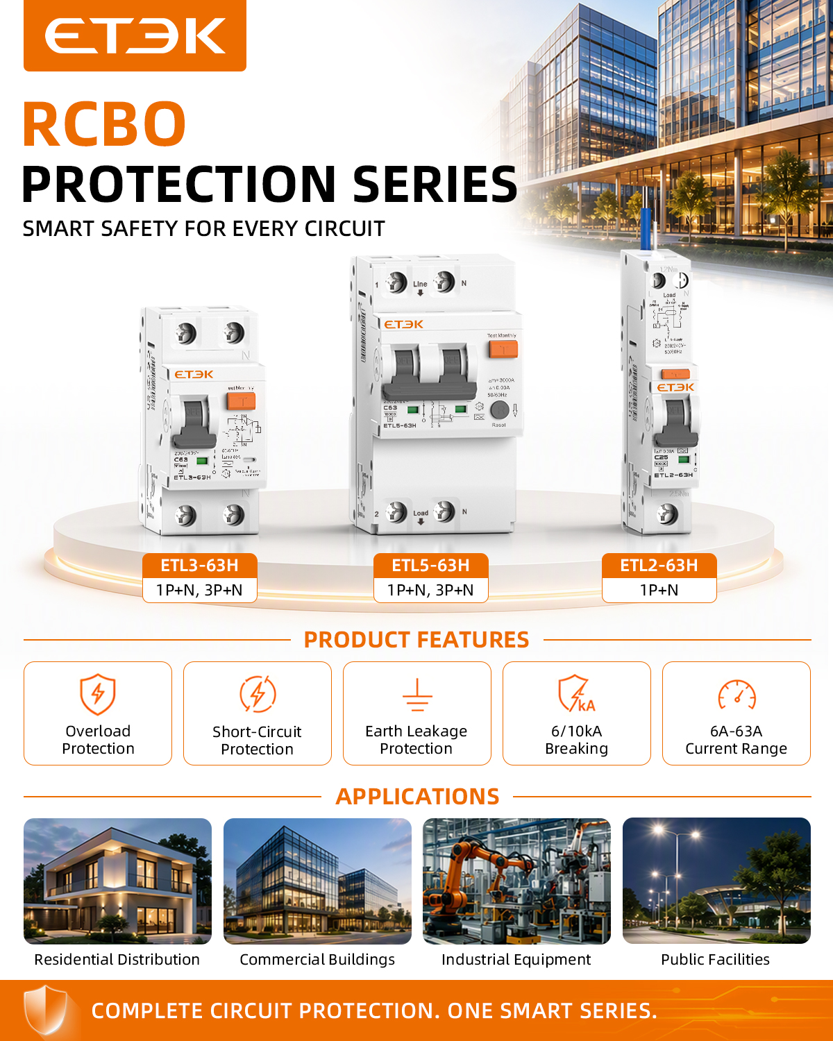
Thermal-magnetic circuit breakers have earned their place as the workhorses of electrical protection. They trip on sustained overloads through a bimetallic strip and on high-magnitude short circuits through a magnetic coil. But this simple, robust design only responds to current. Anything that doesn't push enough current through the breaker's poles—or pushes it in a way the thermal and magnetic elements can't interpret—goes completely unnoticed.
Consider a high-impedance ground fault. The current leaking to earth may be far below the breaker's magnetic pickup, so the thermal element takes minutes or even never reacts. Meanwhile, the fault generates enough heat to start a fire or damage insulation. Or take an arcing fault in a switchboard: the current is chaotic and often below the instantaneous trip threshold, yet the arc flash energy can be lethal. Harmonic currents, phase loss, undervoltage, and overvoltage are also invisible to a thermal-magnetic mechanism, leaving motors, electronics, and variable-speed drives exposed to slow degradation.
Fixed trip curves create another blind spot. A breaker sized for a motor's locked-rotor current may not coordinate well with upstream devices when the load profile changes, leading to nuisance tripping or cascading outages. And since thermal-magnetic units have no way to communicate their status or trip history, maintenance teams are left guessing after an event. Modern electrical systems demand more than just overcurrent and short-circuit protection; they need ground-fault detection, arc-flash mitigation, adjustable time-current characteristics, and real-time monitoring. Relying on thermal-magnetic protection alone leaves too many failure modes unaddressed.
The Hidden Role of Contact Materials in Long-Term Reliability
Most reliability discussions focus on obvious failure modes—cracked solder joints, delaminated boards, blown capacitors. Yet the quiet degradation of contact surfaces often goes unnoticed until a field return lands on the bench. The metal-to-metal interface inside a connector, relay, or switch is a living system, reacting to every power cycle and humidity swing. Tin-plated contacts, for example, develop a thin oxide layer that grows with thermal aging. This layer is initially benign, but repeated micromotion from vibration or thermal expansion can grind it into insulating debris, slowly pushing contact resistance upward long before any visible corrosion appears.
Material choice defines how this microscopic battle unfolds. Gold over nickel remains stable for decades in low-force signal applications, yet gold's softness invites cold welding under high normal loads, leading to transfer and eventual pitting. Silver, prized for conductivity, tarnishes readily in sulfur-rich environments, forming films that puncture only at higher voltages. A less obvious culprit is the underplate—porous nickel can allow base metal migration, while a too-thin precious metal layer wears through after a few dozen mating cycles. These effects are cumulative and nonlinear: a contact that measures 10 milliohms at installation might jump to 50 milliohms after two years of thermal cycling, not because of gross failure, but because fretting corrosion has built a resistive glaze across only a fraction of the apparent contact area.
Field data repeatedly shows that contact-related intermittents spike after seasonal changes, when condensation and temperature swings accelerate both oxidation and micro-motion. The hidden role of materials isn't just about initial conductivity—it's about how the interface ages under real-world stress spectra. Designers who treat contact material as a static spec rather than a dynamic variable inherit reliability problems years down the road. Choosing a harder gold alloy, specifying a thicker diffusion barrier, or switching to a lubricated tin system can shift the degradation curve from early wear-out to end-of-life margin. The contact is only as reliable as the chemistry and mechanics of its outermost atomic layers.
Ask About Endurance Testing: Cycles, Not Just Certificates
Certificates show a product passed a single moment in a lab. They don't tell you what happens after a thousand door slams, a hundred temperature swings, or years of daily friction. If you're comparing hardware, ask for the cycle count behind the badge—how many times was that hinge opened and closed before it loosened? How many hours did the finish hold up under salt spray before corrosion crept in? These are the numbers that separate a sample that survives a demo from a product that survives its actual life.
Manufacturers love to mention compliance with this or that standard, but standards are often minimums designed to catch catastrophic failures, not to measure graceful aging. A drawer slide might meet the industry's 50,000-cycle requirement, yet a competing brand quietly tests to 150,000 cycles and publishes the data. That difference won't show up on a certificate—it only shows up when you ask the right question. Request the test report, look for the actual number of repetitions, and pay attention to what counts as a failure. Some tests stop at 'still functions,' while others measure changes in force, alignment, or noise after the test ends.
Endurance is where design decisions become lived experience. A lock that feels solid on day one might develop a wobble by month eight because the internal spring wasn't rated for extended cycling. A coating that looks pristine in the showroom might chalk and fade after two summers of UV exposure. When you ask about cycles—not just certificates—you're asking how the product will behave when nobody is watching, long after the warranty card has been filed away. That's the question worth asking before you buy, specify, or install anything expected to last.
Temperature Derating: What the Datasheet Won't Tell You
Most engineers glance at a derating curve and assume that if the ambient stays below that knee point, the component will happily deliver its rated power. In practice, the datasheet's "ambient" is a carefully controlled laboratory condition: still air, a standardized test board, and no nearby heat sources. Drop that same part onto a dense PCB packed with regulators, connectors, and a warm FPGA, and the local air temperature right at the package can run ten to twenty degrees hotter than anything you'd measure at the enclosure wall.
The bigger blind spot is thermal resistance. A vendor's RθJA figure usually comes from a board with a specific copper area, often far more generous than what a compact design can spare. Real layouts with thin copper pours, crowded vias, or only a single inner ground plane will see junction temperatures climb much faster than the printed curve suggests. And if your board is mounted vertically, horizontally, or inside a sealed chassis, the convection assumptions behind the derating curve quietly stop applying.
There's also the aging effect no one likes to talk about. Solder joint fatigue, TIM pump-out, and package deformation after repeated thermal cycling can raise thermal impedance over time. A design that works perfectly on day one may start hitting thermal shutdown after a few hundred cycles in the field. So before trusting that derating slope, measure the actual case temperature in your own housing, under your own load profile, with the board mounted the way it will actually ship.
Field Failures Speak Louder Than Lab Reports
Lab reports capture a snapshot under controlled conditions, but the real world keeps throwing variables no test chamber can replicate. Field failures strip away that illusion. They show exactly where a design breaks when temperature swings, vibration, user error, and corrosion gang up at once.
A pump passes every bench test for pressure and seal integrity. Six months later it's leaking on a mine site—not because one parameter exceeded spec, but because abrasive slurry, intermittent dry running, and a maintenance crew's improvised fitting created a failure mode absent from the lab matrix. The field report from that pump carries more weight than a dozen green checkmarks.
Smart engineering teams treat every field failure as an unplanned experiment. They collect the broken parts, trace the root cause, and feed that back into both the next design and the test protocol. The goal isn't to make lab reports pointless—it's to recognize they are only a starting point. When field data contradicts a lab result, the field wins.
FAQ
Space and wiring layout. Many boards are designed with compact RCBOs in mind, but the actual terminal depth and cable entry angles differ. A unit that fits on paper can become a nightmare to wire if the neutral lead is too short or the cage clamp is angled awkwardly. Always ask for a physical sample and test it in a real enclosure before committing to a bulk order.
Look for endurance ratings beyond the basic 4,000 operations. Ask the manufacturer for cycle test data under mixed loads—especially LED drivers and small motors. A reliable unit should maintain consistent trip times after thousands of operations. If the datasheet only mentions electrical life under resistive load, treat that as a red flag.
Modern circuits are full of electronics that can produce smooth DC residual currents or high-frequency leakage. A type AC RCBO may not trip on these at all. If the building has EV chargers, heat pumps, or variable speed drives, you need at least type A, and often type F or B. Choosing the wrong type is not just inconvenient—it can leave a real fault completely undetected.
Don't just look at the nominal 6kA or 10kA figure. The actual prospective short-circuit current at the installation point can be much higher, especially close to the transformer. Ask for the manufacturer's tested conditional short-circuit rating with a backup fuse or breaker. A 6kA unit backed by a 63A fuse might actually handle 25kA safely, but only if the combination is officially tested and listed.
RCBOs are thermal devices, so heat is the enemy. When grouped tightly in a board at 40°C ambient, the internal temperature can rise enough to cause nuisance tripping or reduced lifespan. Ask for derating curves, not just a single operating temperature. A good manufacturer will specify the load reduction needed at 50°C or when devices are mounted side by side without ventilation.
Ask for the full test report from an independent lab, not just the certificate. The report shows actual trip times, energy let-through values, and endurance data. Also request a declaration of conformity that lists the exact production batch and component suppliers. Traceability matters—if a batch has a defect, you want to know exactly which boards are affected.
Yes, especially for maintenance and fault finding. A small green/red window or flag that shows whether the contacts are actually open saves time and reduces risk. Some cheaper units have the handle in the OFF position but the contacts might still be welded shut. A true contact position indicator is driven directly by the moving contact, not just the handle mechanism.
Conclusion
A breaker that trips exactly at the printed curve is useless if it cannot interrupt the fault current it's rated for. Before comparing trip curves, ask the manufacturer for actual breaking capacity tests at the operating voltage you'll use, not just a generic IEC figure. Many RCBOs carry a 6kA rating but behave very differently when short-circuit currents approach that limit. And relying on thermal-magnetic response alone ignores the fact that modern loads produce harmonics, inrush currents, and brief overvoltages that confuse bimetal strips. Electronic residual current detection plus a well-designed magnetic trip can catch faults that a simple thermal element lets slide. Just as important is what's inside the contacts. Silver alloy composition, contact pressure, and arc quenching design determine whether the device welds shut after a handful of trips or keeps opening cleanly for years. Cheaper contact materials often pass a one-time type test but degrade rapidly under repeated switching.
Certificates tell you a product survived a lab sample. Endurance testing tells you how the production line performs after thousands of cycles. Ask for cycle counts under inductive load, not just resistive, and check whether the RCBO is tested for mechanical and electrical endurance together—separate tests hide the wear from arcing and heat. Temperature derating is another blind spot. At 40°C or 55°C inside a crowded distribution board, the rated current drops, but datasheets rarely show that curve. Get the derating table from the manufacturer and compare it with your actual enclosure conditions. Finally, ignore polished failure rates from lab reports. Ask for field return data, common failure modes, and what the company changed in production after those returns. A manufacturer that openly discusses field failures and shows corrective actions is more trustworthy than one that only shares perfect lab certificates.
Contact Us
Contact Person: Andy
Email: [email protected]
Tel/WhatsApp: +86 13356133008
Website: https://www.etek-china.com/